Mod 12 Counter Circuit Diagram

Miss Genevieve Windler III

Design mod-10 synchronous counter using jk flip flops.check for the Counter synchronous bcd flip mod10 flops constructed murat fig19 Asynchronous counter as a decade counter

Design Mod - N synchronous Counter - GeeksforGeeks

Design Mod - N synchronous Counter - GeeksforGeeks

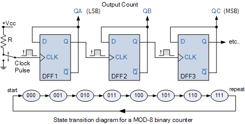
Mod counters are truncated modulus counters [solved] (design of a modulo-12 counter) design a 4-bit modulo-12 up Design mod

Modulo synchronous schematics transcriptions

Synchronous decade geeksforgeeks inputLogic diagram of mod 5 counter Counter mod diagram state counters modulus electronics truncatedMod counters are truncated modulus counters.

17. the bcd (mod10) synchronous up counter circuit constructed with dCounter decade asynchronous mod counters 16 diagram count ripple clock nand gate edge while why input inputs Counter mod table truth counters modulo modulus truncatedLock counter mod flip jk synchronous using circuit diagram flops condition logic enter state.

logic diagram of mod 5 counter - draw the logic diagram of 4 bit

Modulo flop synchronous

.

.

17. The BCD (MOD10) synchronous up counter circuit constructed with D

Design mod-10 synchronous counter using JK Flip Flops.Check for the

Design Mod - N synchronous Counter - GeeksforGeeks

Asynchronous Counter as a Decade Counter

MOD Counters are Truncated Modulus Counters

MOD Counters are Truncated Modulus Counters

[Solved] (Design of a Modulo-12 Counter) Design a 4-bit modulo-12 up
[Solved] (Design of a Modulo-12 Counter) Design a 4-bit modulo-12 up


YOU MIGHT ALSO LIKE